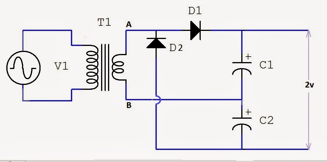
Full Wave Voltage Doubler Circuit Diagram
Solved the circuit depicted in figure 4.4 is a full-wave 12v to 24v voltage doubler circuit Voltage doubler wave circuit half diagram working rectifier capacitor figure
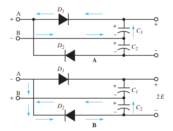
Half-Wave & Full-Wave Voltage Doubler: Working & Circuit Diagram
Voltage doubler and multiplier circuit Diode voltage doubler circuit with tripler and quadrupler explained Voltage doubler 12v 24v how2electronics
Doubler wave
Voltage doubler circuit schematicVoltage doubler wave circuit half two capacitors ac source Voltage doubler: what is it? (circuit diagram, full wave & half waveDoubler voltage circuit diode tripler diagram positive explained half fullwave.
Voltage multiplier circuitsHalf-wave & full-wave voltage doubler: working & circuit diagram Doubler circuit diodes capacitorsDiode voltage doubler circuit with tripler and quadrupler explained.

Voltage multipliers
Dc voltage doubler and voltage multiplier circuits workingVoltage doubler circuit diode diagram half tripler wave cycle diodes explained two Voltage doubler circuit dc diagram wave ac working schematic diode fullwave simple circuits supplyFull wave voltage doubler circuit.
Doubler multiplier 120v eleccircuit circuitsVoltage doubler wave half multiplier tripler multipliers Multiplier circuit doubler rmcybernetics wave schematic bil bunu hv gönderen zaman triplerWave voltage doubler supply power transformer could use 10r 1uf voltages disregard.

Voltage half multiplier doubler wave positive introduction capacitor c2 circuitry remains charged uncharged c1 comes gets while only when so
Half-wave & full-wave voltage doubler: working & circuit diagramWhat is voltage doubler? Voltage doubler circuit (half & full wave)Doubler anyanwu obvious.
Voltage multipliersHalf wave voltage doubler circuit (anyanwu et al, 1983) it should be [solved] the components of full-wave voltage doubler circuit areVoltage doubler wave half difference between circuit using schematic diodes circuitlab created.

Voltage doubler wave half multipliers
Voltage doubler half wave circuit diagram output doublers dc electrical4u double ac working through go nowVoltage multiplier circuits Introduction to voltage multiplierVoltage doubler circuit wave half multiplier diagram ac tripler input frequency circuits ripple hz mains circuitdigest.
Voltage doubler circuit wave halfFull wave voltage doubler using diodes Voltage doubler multiplier circuits circuit wave diagram diode high rectifier half tripler inverter load diagrams circuitdigestVoltage doubler wave circuit diagram half working figure electricalacademia polarity.

Voltage doubler wave half circuit positive cycle capacitor diode d2 ac during thus reverse biased becomes open between electronicscoach
What is a voltage double? definition, half wave voltage doubler, fullVoltage doubler wave diodes using articles related engineeringtutorial What is voltage doubler?Doubler voltage wave half circuit diagram bridge.
What could i use this transformer for ?Voltage doubler: what is it? (circuit diagram, full wave & half wave Doubler circuit electrical4uHalf-wave & full-wave voltage doubler: working & circuit diagram.

Voltage doubler wave which cadence capacitance values matter does 10uf correctly simulated initially c2 c1 had
.
.


